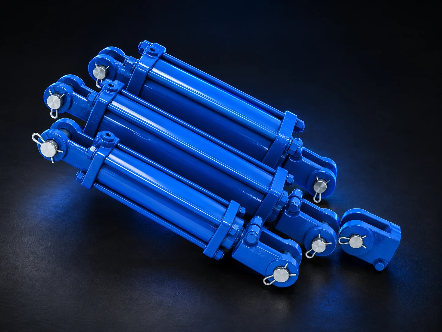
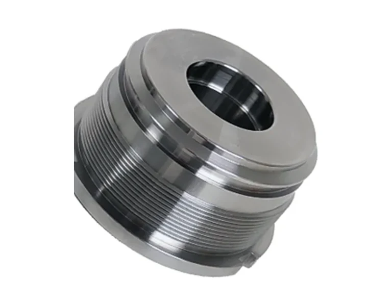
Cylinder Components & Mountings.
Rods, tubes, mounts and associated cylinder components.
Need help matching this part?
Speak to our technical team
Get the right configuration.
Final specifications, compatibility and availability are confirmed against your selected part and operating conditions.
Bore, rod diameter and stroke
Working pressure and required force
Mounting arrangement and closed length
Seal material, environment and drawing
Cylinder barrel tubing exact stock selection.
ST 52 B mechanically burnished cylinder-barrel stock by inside diameter, outside diameter and wall thickness. Stock dimensions do not establish a finished-cylinder pressure rating. Confirm material certification, tolerance, straightness and bore surface finish for the cylinder design.
| Part code | Finish | Inside diameter mm | Mass kg per m (kg/m) | Material reference | Outside diameter mm | Wall thickness mm |
|---|---|---|---|---|---|---|
| MHT 40x50MM | mechanically burnished | 40 | 5.55 | ST52B | 50 | 5 |
| MHT 50x60MM | mechanically burnished | 50 | 6.78 | ST52B | 60 | 5 |
| MHT 63x76MM | mechanically burnished | 63 | 11.14 | ST52B | 76 | 6.5 |
| MHT 80x90MM | mechanically burnished | 80 | 10.48 | ST52B | 90 | 5 |
| MHT 80x100MM | mechanically burnished | 80 | 22.18 | ST52B | 100 | 10 |
| MHT 100x120MM | mechanically burnished | 100 | 27.11 | ST52B | 120 | 10 |
| MHT 100x130MM | mechanically burnished | 100 | 42.52 | ST52B | 130 | 15 |
| MHT 120x140MM | mechanically burnished | 120 | 32.04 | ST52B | 140 | 10 |
| MHT 120x150MM | mechanically burnished | 120 | 49.91 | ST52B | 150 | 15 |
Chrome rod exact stock selection.
CK 45 chrome rod stock by diameter and mass per metre. Confirm chrome thickness, hardness, straightness, diameter tolerance and surface roughness. Rod diameter alone does not establish cylinder force, buckling capacity or seal suitability.
| Part code | Mass kg per m (kg/m) | Material reference | Rod diameter mm | Surface |
|---|---|---|---|---|
| SCHR 16MM | 1.58 | CK45 | 16 | chrome plated; thickness/roughness not established |
| SCHR 25MM | 3.85 | CK45 | 25 | chrome plated; thickness/roughness not established |
| SCHR 32MM | 6.31 | CK45 | 32 | chrome plated; thickness/roughness not established |
| SCHR 40MM | 9.86 | CK45 | 40 | chrome plated; thickness/roughness not established |
| SCHR 50MM | 15.41 | CK45 | 50 | chrome plated; thickness/roughness not established |
| SCHR 60MM | 22.18 | CK45 | 60 | chrome plated; thickness/roughness not established |
| SCHR 80MM | 39.44 | CK45 | 80 | chrome plated; thickness/roughness not established |
| SCHR 100MM | 61.62 | CK45 | 100 | chrome plated; thickness/roughness not established |
| SCHR 150MM | 138.65 | CK45 | 150 | chrome plated; thickness/roughness not established |
| SCHR 1" | 3.98 | CK45 | 25.4 | chrome plated; thickness/roughness not established |
| SCHR 2" | 15.9 | CK45 | 50.8 | chrome plated; thickness/roughness not established |
| SCHR 3" | 35.78 | CK45 | 76.2 | chrome plated; thickness/roughness not established |
Cylinder threaded fork labelled dimensions.
Cylinder clevis dimensions retain the drawing letter references. Use the original dimensional drawing to confirm installation and pin geometry. The ambiguous two-value P entry is not a confirmed drilling diameter. Material, welding requirements and permissible load require confirmation.
| Part code | Dimension h mm | Dimension l mm | Dimension q mm | Dimension w mm | Dimension z1 mm | Dimension z mm | P dimension | Thread f |
|---|---|---|---|---|---|---|---|---|
| CON TFCLM16X15 | 16 | 55 | 35 | 16 | 24 | 39 | 16, 20 | M16×1.5 |
| CON TFCLM20X15 | 20 | 65 | 40 | 20 | 30 | 45 | 20, 25 | M20×1.5 |
| CON TFCLM24X2 | 25 | 75 | 50 | 25 | 30 | 50 | 25, 25 | M24×2 |
| CON TFCLM30X2 | 30 | 95 | 60 | 30 | 35 | 65 | 30, 25 | M30×2 |
| CON TFCLM33X2 | 35 | 110 | 70 | 35 | 40 | 75 | 35, 25 | M33×2 |
Cylinder weldable fork labelled dimensions.
Cylinder clevis dimensions retain the drawing letter references. Use the original dimensional drawing to confirm installation and pin geometry. The ambiguous two-value P entry is not a confirmed drilling diameter. Material, welding requirements and permissible load require confirmation.
| Part code | Dimension h mm | Dimension l mm | Dimension q mm | Dimension r mm | Dimension w mm | Dimension z1 mm | Dimension z mm | P dimension |
|---|---|---|---|---|---|---|---|---|
| CON WFCL16P | 16 | 50 | 35 | 16 | 16 | 24 | 34 | 16, 20 |
| CON WFCL20P | 20 | 60 | 40 | 20 | 20 | 30 | 40 | 20, 25 |
| CON WFCL25P | 25 | 70 | 50 | 25 | 25 | 30 | 45 | 25, 25 |
| CON WFCL30P | 30 | 80 | 60 | 30 | 30 | 35 | 50 | 30, 25 |
| CON WFCL35P | 35 | 90 | 70 | 35 | 35 | 40 | 55 | 35, 25 |